


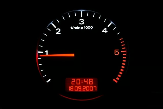
If your boat does not already have a tachometer installed, you're only getting a partial picture of your boat's performance. You may never have come close to testing the limits of your boat's performance to learn what she would do. Adding a tachometer to your boat's instrument cluster allows you to push your boat's motor to the limit specified by the manufacturer--called "wide open throttle" in the motor operator's manual--without overstepping that boundary, thus preventing the engine from hemorrhaging internally.
Items you will need
Wire crimper, pliers-type
Wire, stranded copper 18-gauge AWG, Red
Wire, stranded copper 18-gauge AWG, Green
Wire, stranded copper 18-gauge AWG, Gray
Ring connectors
Blade disconnects
Screwdriver
Soldering iron
Silver core solder
Disconnect the boat's battery.
Strip 1/2-inch of insulation from both ends of all the wires. Use a pliers-type crimper to crimp ring connectors to both ends of the one of the red wires and the black wire and one end of each of the gray wires. Crimp a female blade disconnect onto one end of the remaining red wire and a ring connector to the other end.
Loosen the nut on the "NEG" post of an instrument adjacent to the tachometer location that's activated by the ignition switch. Slip one of the ring connectors on one of the red wires onto the post, thread the nut back onto the post and tighten. Slip the connector on the other end of the wire over the tachometer post marked "BAT."
Slip one of the ring connectors on the green wire onto the terminal post on the back of the tachometer marked "GND." Remove one of the screws on the boat's common ground, slip the connector on the other end of the black wire over that screw and thread the screw back into the common ground, tightening the screw with a screwdriver.
Slide the female blade disconnect onto the male blade disconnect on the back of the tachometer. Attach the ring connector on the other end to the "POS" or "+" post of an adjacent, lighted instrument.
Solder the bare ends of each of the gray wires to the bare ends of the wires coming from the sending unit with a soldering iron and silver core solder. Connect the ring terminal of one of the gray wires to the "GND" connection on the back of the tachometer and the ring terminal of the other gray wire to the "SIGNAL" terminal of the tachometer.